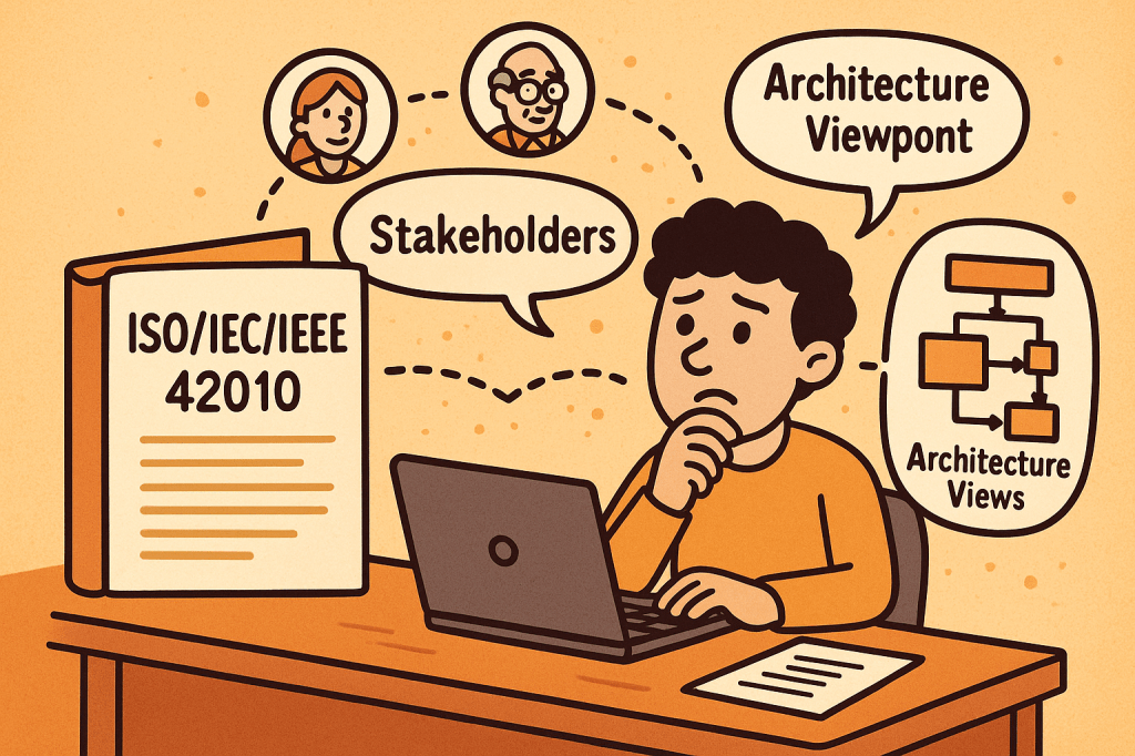
What is ISO/IEC/IEEE 42010?
ISO/IEC/IEEE 42010 is an international standard that provides guidance for describing system and software architectures. It ensures that architecture descriptions are consistent, comprehensive, and understandable to all stakeholders.
The standard defines a framework and terminology that helps architects document, communicate, and evaluate software and systems architectures in a standardized and structured way.
At its core, ISO/IEC/IEEE 42010 answers the question: How do we describe architectures so they are meaningful, useful, and comparable?
A Brief History of ISO/IEC/IEEE 42010
The standard evolved to address the increasing complexity of systems and the lack of uniformity in architectural documentation:
- 1996 – The original version was published as IEEE Std 1471-2000, known as “Recommended Practice for Architectural Description of Software-Intensive Systems.”
- 2007 – Adopted by ISO and IEC as ISO/IEC 42010:2007, giving it wider international recognition.
- 2011 – Revised and expanded as ISO/IEC/IEEE 42010:2011, incorporating both system and software architectures, aligning with global best practices, and harmonizing with IEEE.
- Today – It remains the foundational standard for architecture description, often referenced in model-driven development, enterprise architecture, and systems engineering.
Key Components and Features of ISO/IEC/IEEE 42010
The standard defines several core concepts to ensure architecture descriptions are useful and structured:
1. Stakeholders
- Individuals, teams, or organizations who have an interest in the system (e.g., developers, users, maintainers, regulators).
- The standard emphasizes identifying stakeholders and their concerns.
2. Concerns
- Issues that stakeholders care about, such as performance, security, usability, reliability, scalability, and compliance.
- Architecture descriptions must explicitly address these concerns.
3. Architecture Views
- Representations of the system from the perspective of particular concerns.
- For example:
- A deployment view shows how software maps to hardware.
- A security view highlights authentication, authorization, and data protection.
4. Viewpoints
- Specifications that define how to construct and interpret views.
- Example: A UML diagram might serve as a viewpoint to express design details.
5. Architecture Description (AD)
- The complete set of views, viewpoints, and supporting information documenting the architecture of a system.
6. Correspondences and Rationale
- Explains how different views relate to each other.
- Provides reasoning for architectural choices, improving traceability.
Why Do We Need ISO/IEC/IEEE 42010?
Architectural documentation often suffers from being inconsistent, incomplete, or too tailored to one stakeholder group. This is where ISO/IEC/IEEE 42010 adds value:
- Improves communication
Provides a shared vocabulary and structure for architects, developers, managers, and stakeholders. - Ensures completeness
Encourages documenting all stakeholder concerns, not just technical details. - Supports evaluation
Helps teams assess whether the architecture meets quality attributes like performance, maintainability, and security. - Enables consistency
Standardizes how architectures are described, making them easier to compare, reuse, and evolve. - Facilitates governance
Useful in regulatory or compliance-heavy industries (healthcare, aerospace, finance) where documentation must meet international standards.
What ISO/IEC/IEEE 42010 Does Not Cover
While it provides a strong framework for describing architectures, it does not define or prescribe:
- Specific architectural methods or processes
It does not tell you how to design an architecture (e.g., Agile, TOGAF, RUP). Instead, it tells you how to describe the architecture once you’ve designed it. - Specific notations or tools
The standard does not mandate UML, ArchiMate, or SysML. Any notation can be used, as long as it aligns with stakeholder concerns. - System or software architecture itself
It is not a design method, but rather a documentation and description framework. - Quality guarantees
It ensures concerns are addressed and documented but does not guarantee that the system will meet those concerns in practice.
Final Thoughts
ISO/IEC/IEEE 42010 is a cornerstone standard in systems and software engineering. It brings clarity, structure, and rigor to how we document architectures. While it doesn’t dictate how to build systems, it ensures that when systems are built, their architectures are well-communicated, stakeholder-driven, and consistent.
For software teams, enterprise architects, and systems engineers, adopting ISO/IEC/IEEE 42010 can significantly improve communication, reduce misunderstandings, and strengthen architectural governance.


Recent Comments